Detail - Ankle
|
|
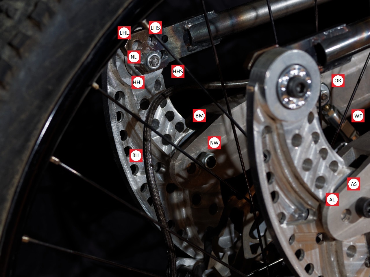
| LHL |
Low BB - Heel Long WB This is the LOW BB, Long Wheelbase configuration as affected by the HEEL pivot location. You'll notice the offset in the drilling of these mounting holes v. the HIGH BB configuration; this can be explained by arcs and Frigonometry... let's just say that it was intended to allow one change at a time.
|
| LHS |
Low BB - Heel Short WB This is the SHORT Wheelbase position equated to the LOW BB configuration |
| HHL |
High BB - Heel Long WB This is the intended mounting position. It is going to sound weird but the LONG Wheelbase position at the HEEL is used for two of the four Wheelbase options. The Wheelbase can be configured for: Long, Short, Extra Long, Extra Short. The prototype Wheelbase was intended to be and is configured as Extra Short. This Requires that the HEEL position be mounted in the LONG setting. This gives me an unweighted Wheelbase of 16.75". I call this extra short since it is a 1/2" shorter than the geometry of the bike that it was replacing. I will include a chart to show Wheelbase Configurations.
|
| HHS |
High BB - Heel Short WB This setting allows for both SHORT and EXTRA LONG Wheelbase configurations
|
| NL |
Nylon Locking Nut Bolts Don't Rattle Tight - Me, over and over.
|
| BH |
Brake Hose Maybe I over think things. The initial concern that I had when I came up with the design of the invention was that I may have to include an extra-long brake hose with each frame. As it turns out I was able to route the brake hose in a way to avoid many issues of frame rub, kinking or excessive bending of the hose while maintaining a typical brake hose length. I had most of it figured out in about 15 minutes. I spent, on and off, at least 100 hours agonizing over whether I could come up with a routing that would be favorable. When it came time to make the cable and hose guides I was very tired of machining. I would make some fine tuning adjustments to the cable routing - including correcting a miscommunication between my welding team and me with regard to the placement of one of the guides. Trapped in my mind for 100 hours over the span of four years I would give my cable routing a 95% for a prototype. I have yet to see better from anyone else; I would insist on correcting the issues for a production model.
|
| BM |
Bad Machining What's a Mill? Here I cut too deep into the foot. I think my idea of an acoustic stop failed me (or I failed my idea with my implementation).
|
| NW |
No Washer I normally insist not only in using washers to spread load, protect the material and isolate rotational force but I also wrote up a section of the frame manual dedicated to which orientation you were intended to select for the washers in the frame. I can't remember why I didn't use washers. It might have been bolt length, recess diameter, maybe proving a point - like tightrope walking without a net. If you've ever worked with me and I've ever given you the lecture about "washers have two sides" then you know I finish off with - "I don't know anyone else that cares". Here I didn't use a washer and I can't remember why.
|
| AL |
Ankle Long WB This hole was really only drilled for the purpose of jigging the leg... I mean allows for both the LONG and EXTRA LONG Wheelbase configurations.
|
| AS |
Ankle Short WB I plunged this hole with an endmill after Welding and Heat Treating. This was the intended mounting position, the other was only for jigging and advertising. If deformation occurred during Welding and Heat Treating (and oh wow did it ever) then I would be able to compensate by making prototype level adjustments after the deformation... not acceptable for mass production, perfect for prototyping. I had this plan established but was encouraged that I was on to something when my Go To photographer told me the story about the deference between mass produced automobiles and one off sports cars. Apparently mass production was enabled by loosening tolerances such that parts could be interchangeable as opposed to the one off every part matches the given unit perfectly.
|
| OR |
O-Ring Seal I rode a BB7. This O-ring not only seals the rod end from contamination, it provides a bumper against vibration. This floating brake mechanism is nearly silent. Even the inherent noise of a rod end going from unloaded to load is dampened by this O-Ring.
|
| We |
Wrench Flats This is a round bar cutoff from the 7075-T6 axle that I made. The rod ends thread into it and they are held in place using jamb nuts at each end. I know from BB7 floater conventions that you only need one jamb nut but I wanted to ensure that there was no movement between the steel rod end and the aluminum link. I cut 8mm wrench flats into the centre of the link to ensure that each end could be adjusted for rotational position independently.
|